General Information
Our main customers are all businesses that use lifting gear, particularly smelters, foundries and steel mills, transhipment and dockyard companies, shipyards, coking installations, the cement industry, etc. Our conductors and components have a current capacity which meets our customers requirements at the most demanding conditions.
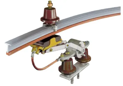
System Overview
Connector
Conductors are connected using rigid joints or expansion joints. We recommend that you clean all contact surfaces and apply a thin coat of contact grease. Expansion joints are not required for a system length of up to 100 m. Expansion joints are installed at high temperature fluctuations and a system length of more than 100 m (this can be determined separately for each system). An insulator must be mounted 250 mm from the expansion joint.
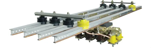
Feeder Clamps
Feeder clamps are mounted at the intended feed points. The contact surfaces must be clean, and a thin coat of contact grease applied.
Locating Clamps
In order achieve controlled expansion of the conductor, fixpoints must be Created. For this purpose, two locating clamps are placed to either side of the insulator. Fixpoints are always cantered between two expansion joints.
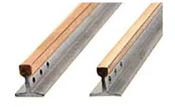
These conductors have proven an outstanding success for safe power feeding of: Travelling cranes, Loading bridges, Container handling equipment, Monorails, Hoists, Coking machinery and many other applications. The Copperhead Conductor Rails are available in sizes to meet individual current requirements from 200 to 4000 Amps.
The main users are: Steel mills, Coking plants, Gas works, Cement industries, Ship yards and Dockside enterprise, Transit and People Mover System.
Some Advantages of CMK Rail Systems
With CMK Systems you can eliminate all drawbacks inherent in the conventional design of trolley wires, steel angles and steel rails.
- Copperhead Rails ensure an efficient and continuous contact.
- There is no sparking.
- The easy maintenance is a proven low factor.
- No losses due to interruption of service, no downtime.
- Negligible wear - almost unlimited life of conductors.
- Much lower resistance between copperhead and carbon pick-up shoe.
Adequate Ampere Capacity must be provided to carry the anticipated electrical loads:
Total Ampere load is determined from the nominal rated full load current reduced by the duty cycle (/ED) and a diversity factor for non-simultaneous operation. The average crane motor duty cycle is usually between 40% and 60%, depending on the type of application. A diversity factor of 0.4 to 0.7 can be used when there are more than one crane on the same runway.
Example
- 3 cranes, each In = 300 Amps.
- Length of runway: 100m (330')
- Assumed duty cycle: 60% (ED)
- Assumed diversity factor: 0.7
- Ampere load per crane: InxfED=300AX0.78=234 A
- Ampere load for 3 cranes = 234Ax3 = 702 A
- TOTAL Ampere load when using a diversity factor of 0.7: 702Ax0.7 = 491.4 A
- Selected conductors: F35/100 or F45/50
Formula for Voltage Drop Calculation
AC: Δu = √ 3 x 1 x 1 x z
DC: Δu = 2 I x 1 R
Δu = Voltage drop [V]
R = Resistance [ohm/m]
I = Ampere load [A]
L = Length from Power feed to end of conductor [m]
z = Impedance [ohm/m]
L = System Length [m]
Selection of Conductors
| Duty Cycle | FED |
|---|---|
| 100% | 1.00 |
| 80% | 0.90 |
| 60% | 0.78 |
| 50% | 0.71 |
| 40% | 0.63 |
Other Criterion:
Select the conductor, cross section to carry the calculated total Ampere load and consider the voltage drop calculation to maintain the limits established by the motor manufacturers. The conductor size and/or number of feed points should be increased in case the drop is exceeding the limitations. For very high Ampere loads, it may be necessary to provide booster cables.
Specify the correct CMK conductor by considering the type of application and environment, such as heavy or light duty service, corrosion, heat, humidity, internal standards.
Effective Length
- I=L power feed located at the end of the system
- I=L/2 power feed located at the mid-point of the system
- I=L/4 power feed located at both ends of the system
- I=L/6 power feed located at L/6 from each end of the system
Engineering Data
| Conhuctor Type | Maximum Continuous Amps. | Resistance Ohm/1000m | Impendence* Ohm/1000m |
|---|---|---|---|
| CMK/F 45/ 50 | 495 | 0.178 | 0.266 |
| CMK/F 45/ 100 | 620 | 0.119 | 0.223 |
| CMK/F 45/ 150 | 728 | 0.089 | 0.203 |
| CMK/F 45/ 200 | 826 | 0.072 | 0.194 |
| CMK/F 45/ 300 | 1000 | 0.051 | 0.182 |
| CMK/F 45/ 400 | 1156 | 0.040 | 0.174 |
| CMK/F 45/ 500 | 1299 | 0.033 | 0.169 |
| CMK/F 45/ 600 | 1432 | 0.028 | 0.165 |
| CMK/F 45/ 700 | 1582 | 0.023 | 0.0681 |
| CMK/F 45/ 800 | 1725 | 0.018 | 0.0445 |
| CMK/F 45/ 1000 | 1869 | 0.013 | 0.0209 |
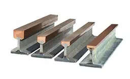
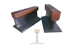
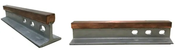
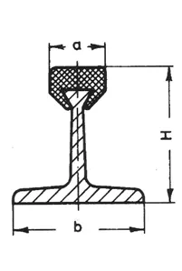
Steel - Copperhead Rails
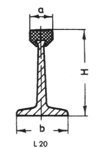
| TYPE | Copper Cross section mm2 | Steel Cross section mm2 | Equival. Total Copper Conhuctor mm2 | H mm | a mm | b mm | Weight Kg/m | Max. Continuous A |
|---|---|---|---|---|---|---|---|---|
| CMK/L 20/ 14-7 | 14 | 150 | 36 | 31 | 6.5 | 20 | 1.24 | 220 |
| CMK/L 20/ 25-7 | 25 | 150 | 47 | 33 | 8 | 20 | 1.34 | 256 |
| CMK/L 20/ 50-7 | 50 | 150 | 72 | 34 | 10 | 20 | 1.57 | 327 |
| CMK/L 20/ 100-7 | 100 | 150 | 122 | 38.5 | 12 | 20 | 2.02 | 444 |
Standard Lengths:
7 m (23')
Main application:
Conductor system for hoists and monorails, down-shop and cross travel supply for light cranes
Best applicable collectors:
IEP/DVD 1 and IEP/DVD
| TYPE | Copper Cross section mm2 | Steel Cross section mm2 | Equival. Total Copper Conhuctor mm2 | H mm | a mm | b mm | Weight Kg/m | Max. Continuous A |
|---|---|---|---|---|---|---|---|---|
| CMK/F 35 /30-7 | 30 | 265 | 69 | 32 | 14.2 | 35 | 2.34 | 320 |
| CMK/F 35/ 50-7 | 50 | 265 | 89 | 33.1 | 14.6 | 35 | 2.52 | 410 |
| CMK/F 35/100-7 | 100 | 265 | 139 | 36.0 | 15.3 | 35 | 2.97 | 529 |
| CMK/F 35/150-7 | 150 | 265 | 189 | 38.3 | 17.3 | 35 | 3.42 | 632 |
| CMK/F 35/200-7 | 200 | 265 | 239 | 40.8 | 17.3 | 35 | 3.87 | 724 |
Standard Lengths:
7 m (23')
Main application:
Conductor system for heavy and monorails, down-shop and cross travel supply for medium duty cranes
Best applicable collectors:
CMK/GSV 1, CMK/GSV 2, CMK/GSV 4 and CMK/GSV 8
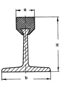
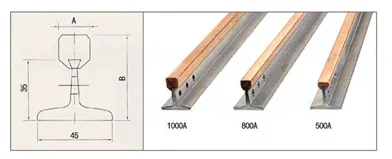
| TYPE | Copper Cross section mm2 | Steel Cross section mm2 | Equival. Total Copper Conhuctor mm2 | H mm | a mm | b mm | Weight Kg/m | Max. Continuous A |
|---|---|---|---|---|---|---|---|---|
| CMK/F 45/ 50-7 | 50 | 355 | 102 | 41.1 | 14.6 | 45 | 3.23 | 495 |
| CMK/F 45/ 100-7 | 100 | 355 | 152 | 46.0 | 15.3 | 45 | 3.68 | 620 |
| CMK/F 45/ 150-7 | 150 | 355 | 202 | 48.3 | 17.3 | 45 | 4.13 | 728 |
| CMK/F 45/ 200-7 | 200 | 355 | 252 | 50.08 | 17.3 | 45 | 4.58 | 826 |
| CMK/F 45/ 300-7 | 300 | 355 | 352 | 56.3 | 17.6 | 45 | 5.48 | 1000 |
| CMK/F 45/ 400-7 | 400 | 355 | 452 | 59.3 | 19.6 | 45 | 6.38 | 1156 |
| CMK/F 45/ 500-7 | 500 | 355 | 552 | 64.3 | 19.6 | 45 | 7.28 | 1299 |
| CMK/F 45/ 600-7 | 600 | 355 | 652 | 65.0 | 23.2 | 45 | 8.18 | 1432 |
Standard Lengths:
7 m (23')
Main application:
Conductor system for heavy and monorails, down-shop and cross travel supply for medium duty cranes
Best applicable collectors:
CMK/GSV 1, CMK/GSV 2, CMK/GSV 4 and CMK/GSV 8